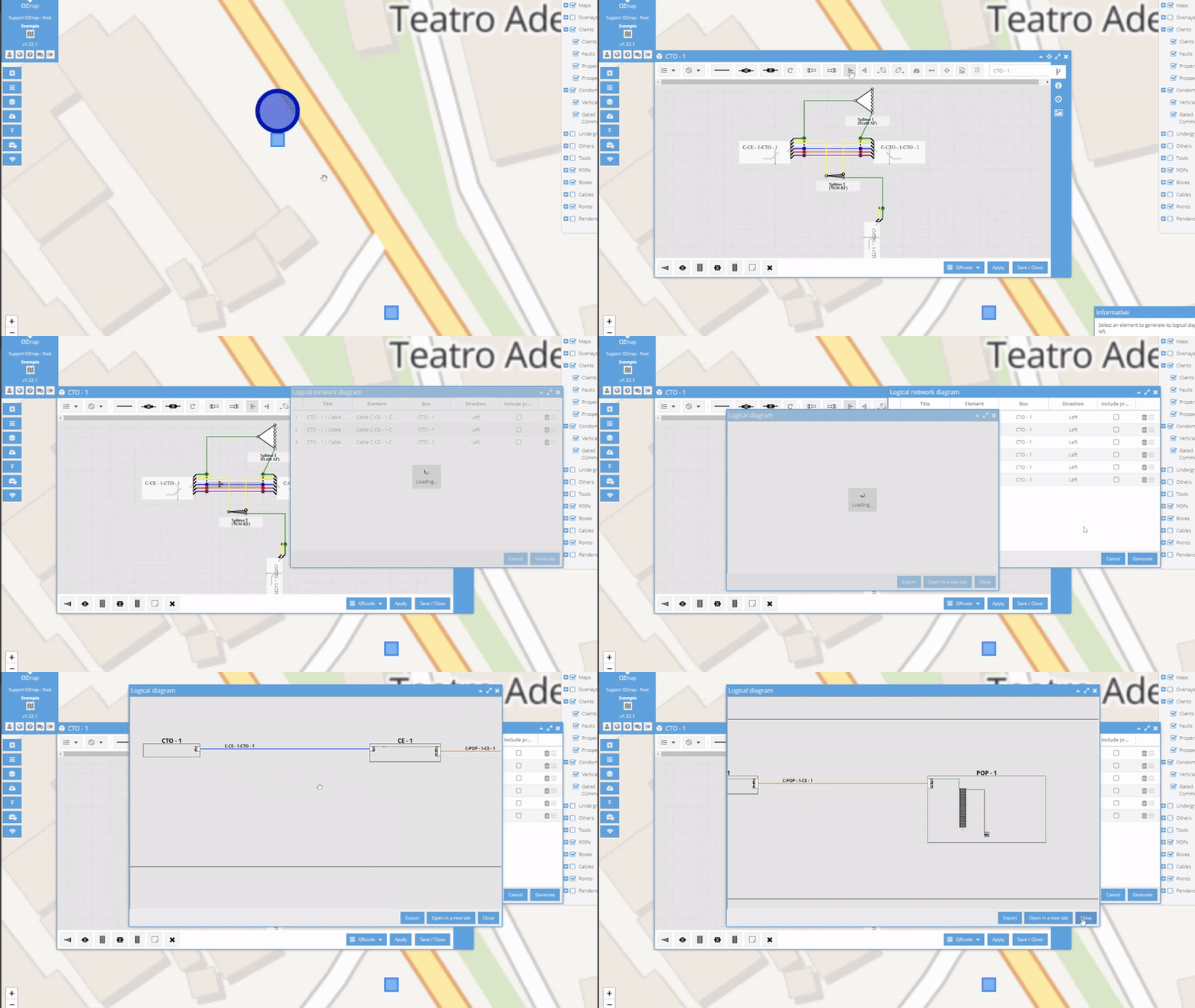
The logical diagram shows the connections between the boxes and the connections within the box, displaying all the illuminated elements along that path.

Generating a logical diagram
To generate a logical diagram in the boxes, simply click on the buttons highlighted in the image below, choosing to generate the diagram to the left or to the right.
 |  |
After selecting the direction in which you want to generate the report, simply choose the fiber or fibers you want to view and click the 'generate' button.

In POP, the process is similar to that of the box. You can select any POP equipment to create the diagram, remembering that in OLT it is only possible to illuminate to the right, as it is the initial element of the diagram.

To export the diagram, simply click on the "Export" button highlighted in the image below.

In addition to generating the diagram of the entire slot on the OLT, you can generate it individually for each port, whether it is the OLT, DIO, etc. Just right-click on the desired port and select the direction for which you want to generate the diagram.

It is possible to select more than one fiber or OLT to generate within the logic diagram. In the case of boxes, you can create the logic diagram of several fibers and in different directions (left and right). In addition, you can rearrange the elements by clicking on the button with three lines, delete an element using the trash can button and choose whether the properties that are along the path will appear in the diagram.
The “Title” column represents the title of the diagram, and you can change it if you wish. The “Element” column refers to the name of the element. The “Box” column refers to the name of the box/POP in which the fiber is inserted. In “Direction” you can check in which direction the report will be generated and in “Include properties” you can choose whether or not to include properties in the diagram.

When generating a diagram with more than one element, they will be organized like this, separated into rectangles, with the name of the corresponding element above the rectangle:

The logic diagram can also be used in OZmob, in the same way as in OZmap. Simply click on the three-dot icon next to the desired fiber name and select the direction of the diagram.

