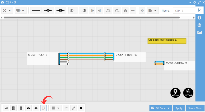
In Ozmap, the Box Editor is the tool used to represent and edit the interior of a box.
Learn More About How to Create a Box – Check Out This Article on Boxes.
Inside a box, the following elements may be present:
Cable
The cables that start or end in the box display the representation of fibers and looses (fiber groupings) shown in the image below. There are three different ways to visualize these fibers: Numbers, Direction, and Derivations. Each of these types can be selected in the upper left part of your box editor, as shown in the photo below.

In the first option, the visualization is based on numbers. It will number your fibers and indicate whether they are receiving a signal or not. If filled, the fiber is receiving a signal from the POP; if there is no signal, the circle will be hollow.

In the second option, the direction of the signal traveling through the fiber will be shown. The arrow indicates where the signal is going, and if it displays a "break" icon, as seen in fibers 4 and 5, it means that the fiber is not receiving a signal.

The last option indicates how the signal is being received. In the first two fibers, a dash is shown, meaning that in previous boxes, the signal was not split by a splitter. Conversely, multiple arrows, as seen in the last two fibers, indicate that the signal has already passed through a splitter. The break icon remains the same as in previous cases, representing a fiber that is not receiving a signal from the POP.

Fiber Information

Fiber information can be viewed in the labels menu of your Box Editor.

By selecting the "Name" option, the names of each fiber will become visible. There is also the option to move these names if you want to highlight a specific fiber.

The process is the same for the "Notes" option. This is very useful for replacing post-its in certain situations. If you want to learn more about how to create notes for your elements within the Box Editor, check the "Element Properties" section.

When activated, the information will appear even in the diagrams exported from inside the box, both in PNG and PDF formats. This is ideal for highlighting any information you wish to send to your technician in the field, for example.

Splitter
Basically, a 1/n optical splitter.
If it is white, it allows connection with the client. If it is gray, it is a network splitter and does not allow client connections. In commercial feasibility analyses in OZloc, only the splitters that allow client service are considered.
Both examples of splitters are shown in the image below.

Connector
An optical connector with two sides.
Just like the splitter, it may or may not allow connection with the client.

Fusion
A fiber fusion inside the box.
It follows the same configuration as the previous items, and may or may not allow connection with the client.

Client
Clients are represented by small rectangles with a connection point, linked to the respective equipment for service. If the rectangle is dotted, it means the client is marked as "not implanted." In cases where this checkmark appears, such as with client 10050, it indicates that the client is "implanted and certified."

An important detail for documentation is that its textual identification can be chosen in the system settings. In this section, you can select whether the client will be identified within the box editor by their name, code, or the name of the drop cable used.

Post-it
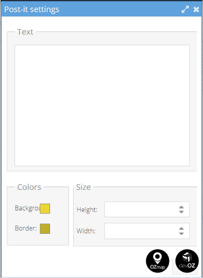
A text field in the shape of a post-it can be used to create comments or free notes inside the box. Additionally, you can configure the color and format of your post-it as desired, either when creating it or through its properties.


Element Properties
Each element inside the box has an editing field, whether it is a splitter, a fusion, a connector, etc.
To open it, simply right-click and go to element properties. There, you can select/edit fields for each element. One of these fields is the comments field.
Ex. Splitter:

When you click save, the comment will appear when hovering over the element, as shown in the image below.

Elements inside a box, following the system's standard, may or may not be implanted.
When not implanted, their borders will be dashed, as shown in the image below.

You can also mark the elements as 'implanted' or 'not implanted' in the box via the area report. Simply select the desired area, go to the equipment tab, select the elements, and click change.
It is also possible to individually lock the splitter ports, preventing connections and sales from being made on them, as well as adding tags, comments, and power.

Edition
When you open a box, you will see both a lower and an upper menu.
In the lower menu, you will find the following icons to add elements and edit the diagram:

Splitter;
Switch;
FPP;
Fusion;
Connector;
Post-it;
Alignments (vertical and horizontal);
Rotate clockwise;
Smart tracing;
Remove elements.
The alignment tool is used to align the equipment within the Box Editor. You can choose to align them vertically or horizontally.

The smart tracing feature allows you to organize your connections in the box more quickly and efficiently. By activating this tool, the system automatically arranges the connections. You can apply the tracing to a single cable or multiple elements simultaneously. To select multiple elements, simply hold down the "Shift" key while selecting the desired items.

Right next to it, we have:

QRcode: generates and exports a QR code for your box, which can be in PDF or PNG format;
Apply: saves the changes to your box without closing the open window, allowing you to continue making changes without needing to reopen the box;
Salve/Close: The changes made will be saved, and the editing window will be closed.
In the top menu:

1. Fiber visualization;
2. Fiber label: has three options, off, name, and note. It is used to keep the fiber's name or note visible in both the Box Editor and the logical diagram export;
3. Multiple Connection: For this, select the first and last element you want to connect in the source fiber, and only the first element in the destination fiber;
4. Multiple Connections using fusion;
5. Multiple Connections using connector;
6. Illuminate to the left/right: you can illuminate the path your fiber takes to the POP or to the client;
7. Logical diagram to the left/right: shows the connections between the boxes and the internal connections of the box;
8. OTDR to the left/right: it is used to identify a specific location (in meters relative to the box) on a fiber;
9. Calculate power: if you want to know the power of fiber and the distance it is covering to the POP, simply select this function and click on the fiber you want;
10. Beginning and end of fiber: with this function, you can determine which box the fiber starts from and which box the fiber ends at;
11. Center elements within the box;
12. Export to .png/.pdf: Export the diagram of your box to PNG or PDF format.
13. You can add your company's logo by simply uploading the desired image in the 'Logo' field of your System Settings.
Route Report
With the beginning and end of the fiber tool, it is possible to extract a report of the entire path it has taken and export this information in KML or CSV/XLS format.


Edit history
The boxes also have a tab where all the changes made within them are listed. They can be accessed through the side icon and display the name of the user who made the edit, along with the date and time the edit was made. Additionally, it is possible to see how the box was configured before and after the change.

To see the differences before and after the update, simply click on the 'i' corresponding to the line you want to view, located in the 'View' column.

Add Images
Additionally, you can assign images to the boxes by accessing the side icon for posts and selecting 'New post'.

Navigating Between Boxes
You can move between boxes using the connecting cables. Just right-click on an element and choose the "Next Box" option. This will also open the next box's window.

